Building a PS/2 mouse header
Post covering how I adapted a PS/2 mouse bracket to fit my FIC PA-2007 motherboard.

Overview
I had a FIC PA-2007 (https://theretroweb.com/motherboards/s/fic-pa-2007) come in to my possession but it didn't come with any of the brackets. Some of them (serial and USB) matched a standard connector I could just buy. However, the PS/2 mouse connector seemed to be non-standard.
The Answer
If you need the motherboard pinout for this exact board, it is below:
Note: PIN 1 is closest to the back of the motherboard
PIN 1 - DATA
PIN 2 - Not present
PIN 3 - Ground
PIN 4 - +5V
PIN 5 - Clock
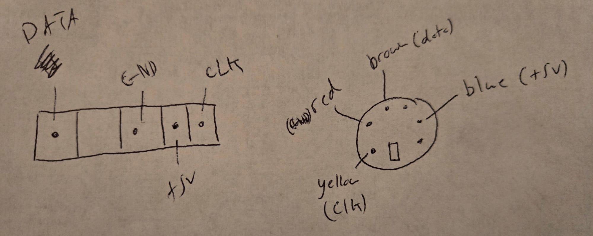
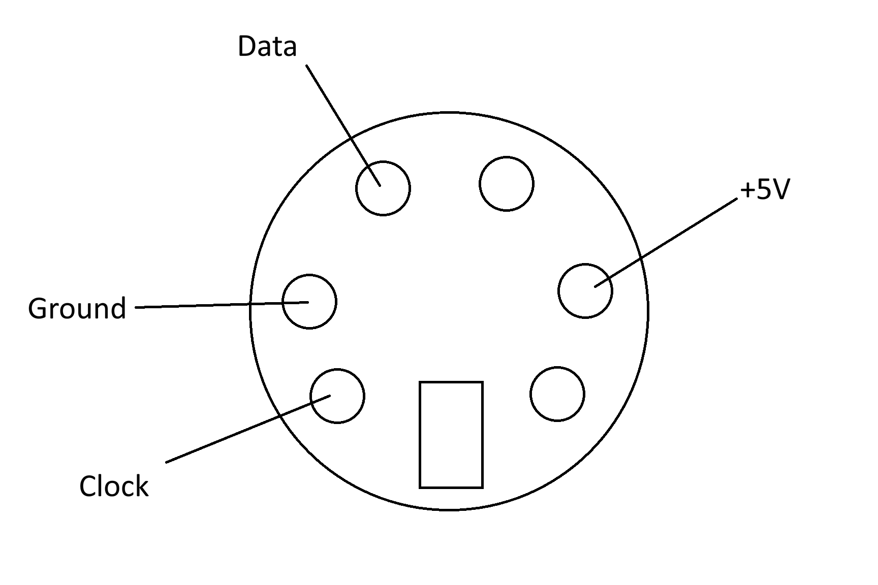
I needed to create a bracket to match what was on the board. I purchased a standard bracket with a 10-pin (5x2) header connector from Amazon. This would work in most later model motherboards. PS/2 mouse connectors only use 4 wires (Ground, +5V, Data, and Clock). I used a small flat head screwdriver to lift up the plastic holding the female pins in the bracket connector. Once those were pulled out, I was able to map them to the correct hole in the connector. You can just add the existing female pins into a new 5x1 pin header connector matching the list above. The diagram below shows the pins on the female (bracket side) connector.
The Process
I tried to keep this simple. If you have only a multimeter, you can track down which pins on the motherboard are which. This should work for other motherboards as well.
Ground
This was the easiest to find. With a multimeter, you can pick one of the Ground wires on the power supply. These are normally black. I checked that against the 4 pins in the connector on the motherboard and identified the corresponding pin.
+5V
This one was trickier because all 3 remaining pins will show a 5V reading with the multimeter. I read that using a 1 kohm resistor would help identify which were +5V and which were Data and Clock. In my testing that didn't work. I had better luck testing for continuity between the +5V pin on an ISA slot and the remaining PS/2 mouse pins on the motherboard. The +5V pin on an ISA slot is B3 where B is the back (non-component) side of the ISA card and pin 3 is the third from the back of the motherboard. Using the multimeter I was able to identify the only pin with good continuity.
Data and Clock
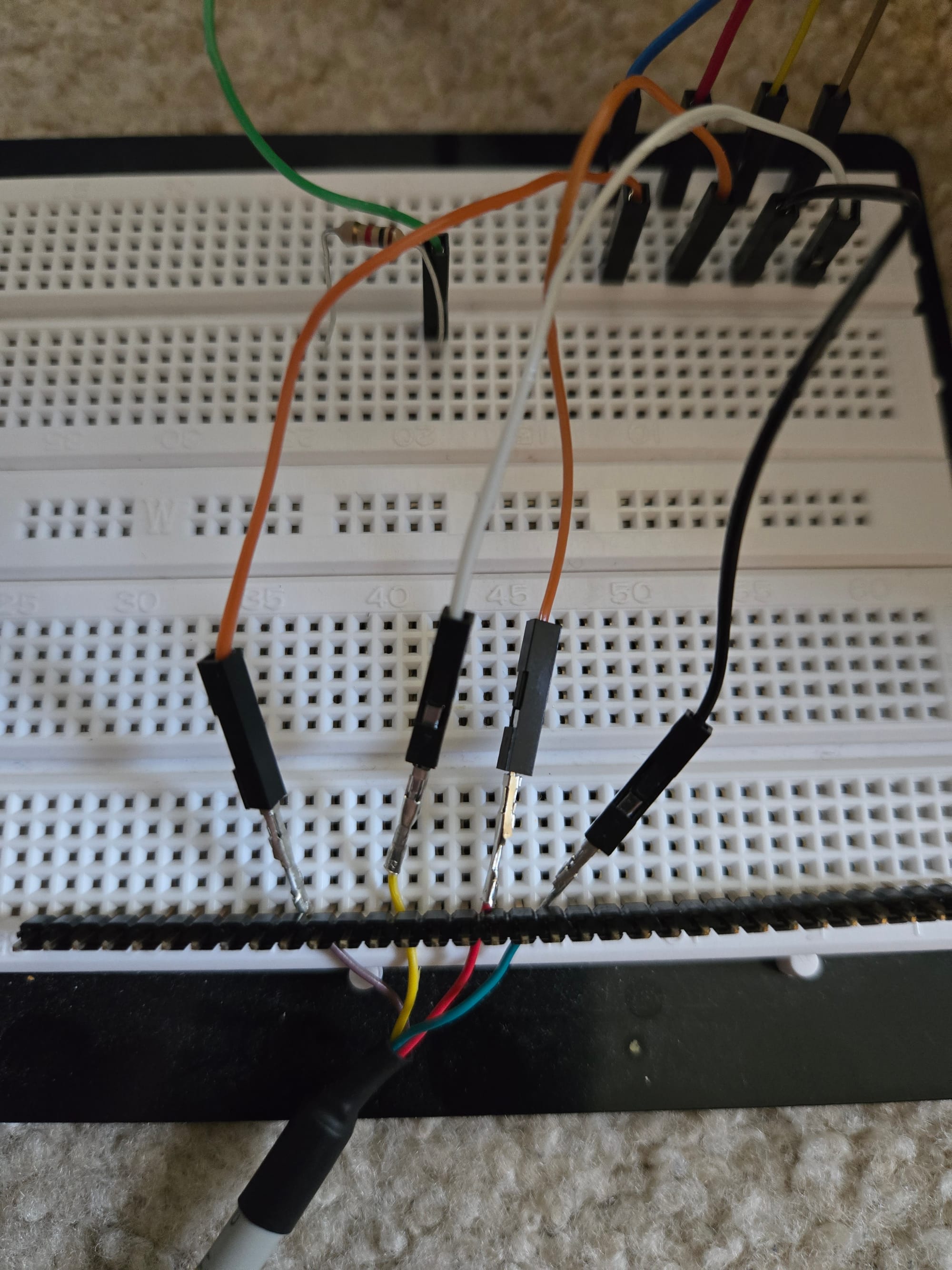
I wasn't able to find a smart way to do this. I tried it both ways using a breadboard. My first attempt resulted in the AT keyboard not working which I thought was weird, but everything worked in the other configuration.